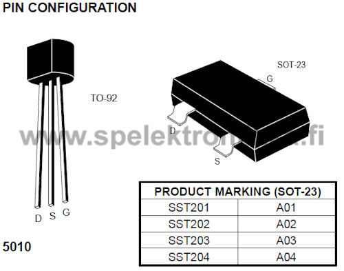
J201-2 Document Number: IF35018.R00 InterFET Corporation June, 2019 InterFET Product Folder Technical Support Order Now J201-2 TO-92 Mechanical and Layout Data Package Outline Data Suggested Through-Hole Layout 1. All linear dimensions are in millimeters. Package weight approximately 0.19 grams 3. Molded plastic case UL 94V-0 rated 4. Since this is a project designed by a community member, it may contain design errors that prevent it from working as intended. OSH Park cannot place any guarantees about.
Type Designator: J201
Type of Transistor: JFET
Type of Control Channel: N -Channel
Maximum Power Dissipation (Pd): 0.625 W
J201 Jfet Smd
Maximum Drain-Source Voltage |Vds|: 40 V
Maximum Gate-Source Voltage |Vgs|: 1.5 V
Maximum Drain Current |Id|: 0.001 A
Maximum Junction Temperature (Tj): 150 °C
Package: TO-92
J201 Transistor Equivalent Substitute - MOSFET Cross-Reference Search
J201 Datasheet (PDF)
0.1. 2sj201.pdf Size:268K _toshiba
2SJ201 TOSHIBA Field Effect Transistor Silicon P Channel MOS Type 2SJ201 High-Power Amplifier Application Unit: mm High breakdown voltage : VDSS = -200 V High forward transfer admittance : |Yfs| = 5.0 S (typ.) Complementary to 2SK1530 Absolute Maximum Ratings (Ta = 25C) Characteristics Symbol Rating UnitDrain-source voltage VDSS -200 VJEDEC Gate-source voltag
J201 Smd

0.2. j201.pdf Size:851K _fairchild_semi
J201 MMBFJ201J202 MMBFJ202GSTO-92GS SOT-23 NOTE: Source & DrainDD are interchangeableMark: 62P / 62QN-Channel General Purpose AmplifierThis device is designed primarily for low level audio and generalpurpose applications with high impedance signal sources. Sourcedfrom Process 52.Absolute Maximum Ratings* TA = 25C unless otherwise notedSymbol Parameter Value Uni
0.3. j201 j202 mmbfj201 mmbfj202 mmbfj203.pdf Size:783K _fairchild_semi
January 2008J201 - J202 / MMBFJ201 - MMBFJ203N-Channel General Purpose Amplifier This device is designed primarily for low level audio and general purpose applications with high impedance signal sources. Sourced from Process 52.TO-92 SOT-2332MarkingMarking J201MMBFJ201 : 62PJ202MMBFJ202 : 62Q1 11. Drain 2. Source 3. Gate 1. Drain 2. Source 3. GateAbsolute
0.4. j201 j202 j204c sst201 sst202 sst204c.pdf Size:78K _vishay
J/SST201 Series Vishay SiliconixN-Channel JFETsJ201 SST201J202 SST202J204 SST204PRODUCT SUMMARYPart Number VGS(off) (V) V(BR)GSS Min (V) gfs Min (mS) IDSS Min (mA)J/SST201 -0.3 to -1.5 -40 0.5 0.2J/SST202 -0.8 to -4 -40 1 0.9J/SST204 -0.3 to -2 -25 0.5 0.2FEATURES BENEFITS APPLICATIONSD Low Cutoff Voltage: J201
0.5. j201 j202 j203 j204 sst201 sst202 sst203 sst204.pdf Size:22K _calogic
N-Channel JFETGeneral Purpose AmplifierCORPORATIONJ201 J204 / SST201 SST204FEATURES ABSOLUTE MAXIMUM RATINGS(TA = 25oC unless otherwise specified) High Input Impedance Low IGSS Gate-Source or Gate-Drain Voltage . . . . . . . . . . . . . . . . -40VGate Current . . . . . . . . . . . . . . . . . . . . . . . . . . . . . . . . . 50mAStorage Temperature Range
0.6. cj201nl.pdf Size:151K _jiangsu
JIANGSU CHANGJIANG ELECTRONICS TECHNOLOGY CO., LTD SOT-23 Plastic-Encapsulate Transistors CJ201NL TRANSISTOR (NPN) SOT23 FEATURES High Collector Current Capability Low Collector-emitter Saturation Voltage High Efficiency Leading to Less Heat Generation 1. BASE Reduced PCB Requirements 2. EMITTER Alternatived Effectively to MOSFETS in Specific Applications
0.7. lj2015-52.pdf Size:105K _china
LJ2015-52FD75C NPN P T =25 75 WCM CI 10 ACMT 150 jmT -55~150 stgV I 2mA 50 V(BR)CBO CBV I 2mA 50 V(BR)CEO CEI V =20V 2 mACBO CBI V =20V 2 mACEO EBV 2.5 VBEsatI =5ACI =0.5AB
0.8. cs7456 lj2015-53.pdf Size:70K _china
LJ2015-53CS7456DP N P T =25 1.9 WD AI V =10V,T =25 5.7 AD GS AI 40 ADMV 20 VGST +150 jmT -55 +150 stgR 65thJA /WR 1.8thJCBV V =0V,I =0.25mA 100 VDSS GS DV =10V,I =9.3A 0.025
Datasheet: JFTJ105, J174, J175, J176, J177, MMBFJ175, MMBFJ176, MMBFJ177, IRF740, J202, MMBFJ201, MMBFJ202, J210, MMBFJ210, MMBFJ211, MMBFJ212, J270.
LIST
Last Update

MOSFET: CEZ3R04 | CEZ3P08 | CES2322 | CEB93A3 | CEF9060N | CEB6086 | CEN2321A | CEN2307A | CEM9288 | CEM6056L | CEM4052 | CEM2192 | CEU25N02 | CED25N02 | CEU20N02 | CED20N02

J201 Smd
Sadly, the through-hole J201 is no longer produced, and remaining supplies from ebay/China are so out of spec, they are not usable. SMD is the solution. The SMD (surface-mount device) version of this JFET is still available, and is produced today by leading chip manufacturers with very high tolerances. Great news right? Well, SMD and DIY don't mix well for most (practically all) people.
Check out the size-comparison picture on this page. The SMD package is the black spec to the 2 pieces of instant rice. A regular through-hole JFET is also pictured. Obviously, these things are tiny. While some builders may have 'some' smd experience, probably none will match the quality of assembly of these factory-produced prefabricated micro-PCBs with the J201 already soldered into place. Beautiful! The same black-spec-transistor is shown next to the pre-soldered boards.
- Factory-soldered smd version of J201 on-board
- Used as a 'tube-replacement' in many DIY circuits that are emulating amplifier tones
- Just use some cut-off leads from a resistor or diode, and solder to the 3 pads and you have a through-hole JFET
- The pads are marked for Drain, Source and Gate, making these super easy to integrate into your main PCB
- Your order will be packed in an Anti-Static bag. Multiple packs might be combined, as seen in image below
- Trusted GuitarPCB Product. If you have bought these from Barry at GPCB, this is the same product.
- Available in 2 size packs. Save when you order the larger pack.
Sorry, we cannot sell in other increments. This item typically ships via first class mail in a bubble mailer unless purchased at the same time as a kit.

J201 Smd Adapter
Please verify JFET orientation when you install into your project. We will not be held responsible for damage due to incorrect usage.
